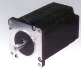
Stepper Motors 60BYGH
NEMA Format 24 (60×60 mm)
 Download data sheet
General specification of stepper motor 60BYGH:
| Step Angle | 1.8° ± 5% |
| Temperature Rise | Δt = max. 80°C |
| Ambient Temperature Range | -20°C – 50°C |
| Insulation Resistance | 100MΩ min. 500V DC |
| Dielectric Strength | 500V AC/1 min |
Electrical specification:
| Model | Motor Length | Holding Torque | Lead Wires | Rated Current | Phase Resis- tance | Phase Induc- tance | Rotor Inertia | Detent Torque | Shaft Ød | Motor Weight | |
| (mm) | (N·cm) | (A) | (Ω) | (mH) | (g·cm2) | (N·cm) | (mm) | (kg) | |||
| 60BYGH250B | B | 56.5 | 147 | 4 | 3.0 | 1.4 | 3.1 | 300 | 9.60 | 8 | 0.77 |
| 60BYGH250B-08* | B | 56.5 | 147 | 4 | 3.0 | 1.4 | 3.1 | 300 | 9.60 | 10 | 0.77 |
| 60BYGH250BA | B | 56.5 | 147 | 4 | 3.0 | 1.4 | 3.1 | 300 | 9.60 | 10 | 0.77 |
| 60BYGH250C1 | B | 77.5 | 270 | 4 | 4.0 | 1.1 | 3.33 | 700 | 12.05 | 8 | 1.34 |
| 60BYGH250D-02B1) | B | 89 | 330 | 4 | 4.2 | 0.73 | 3.3 | 840 | 13.43 | 8 | 1.5 |
| 60BYGH250D-02BR1) | B | 89 | 330 | 4 | 4.2 | 0.73 | 3.3 | 840 | 13.43 | 8 | 1.5 |
| 60BYGH250D-02Y1) | B | 89 | 330 | 4 | 4.2 | 0.73 | 3.3 | 840 | 13.43 | 8 | 1.5 |
| 60BYGH250D-09R**1) | B | 89 | 330 | 4 | 4.2 | 0.73 | 3.3 | 840 | 13.43 | 8 | 1.5 |
| 60BYGH450D-02*1) | U | 89 | 240 | 8 | 3.0 | 1.46 | 3.3 | 840 | 13.43 | 8 | 1.5 |
| BS | 330 | 2.1 | 2.92 | 13 | |||||||
| BP | 330 | 4.2 | 0.73 | 3.3 | |||||||
| 60BYGH450D-03** | U | 89 | 240 | 8 | 3.0 | 1.46 | 3.3 | 840 | 13.43 | 8 | 1.5 |
| BS | 330 | 2.1 | 2.92 | 13 | |||||||
| BP | 330 | 4.2 | 0.73 | 3.3 | |||||||
| 60BYGH250E-021) | B | 101 | 370 | 4 | 3.6 | 1.0 | 3.65 | 1000 | 16 | 8 | 1.72 |
| 60BYGH450E-02A1) | U | 101 | 300 | 8 | 2.3 | 2.2 | 4.8 | 1000 | 16 | 10 | 1.72 |
| BS | 390 | 1.65 | 4.4 | 19.2 | |||||||
| BP | 390 | 3.3 | 1.1 | 4.8 |
Notes:
U = Unipolar Connection
B = Bipolar Connection
BS = Bipolar Series Connection
BP = Bipolar Parallel Connection
* = Stepper motor with 2. shaft (diam. 6.35 x 13.3mm)
** = Stepper motor with 2. shaft (diam. 8.0 x 13.3mm)
1) = Hole pattern same as 57BYGH series
R = Shielded cable + cable grommet
Y = With JST B6P-VH connector
For detailed product data please see single data sheet.
All stepper motors are available with double shaft or with double shaft and encoder.
4-lead wire motors are optional available with shielded cable and shielded round 6-pin connector ready-for-use.
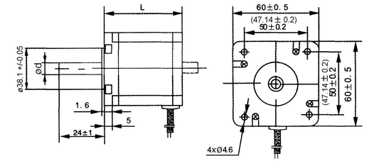
Mechanical Dimensions:
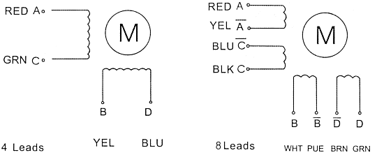
Wiring Diagram
All technical data are subject to change 2012/02
English
