
Stepper motor driver
Leadshine DM805-AI
Digital Technology, max.80V/7.0A
 Download data sheet
 Download software manual
 Download hardware manual
 Download driver software
 Download RS232 pin layout
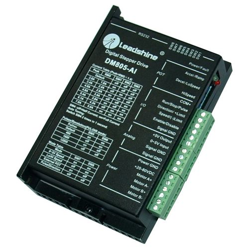
The DM805-AI is a 0 – 5 V input stepper drive with built-in oscillator which is based on the latest digital control algorithm. It brings a unique level of system smoothness, providing optimum torque and nulls mid-range instability. Motor self-test and parameter auto-setup technology offers optimum responses with different motors and easy-to-use. The driven motors can run with much smaller noise, lower heating, smoother movement than most of the drivers in the markets. Its unique features make the DM805-AI an ideal solution for applications that require low-speed smoothness.
The three built-in potentiometers are used to preset and adjust the velocity, acceleration and deceleration. In 0-5 V speed mode, the motor speed is controllable and follows the analog 0 - 5 V input. In high / low speed mode, the motor speed is selected by digital input and adjusted by the high/low speed potentiometers. The user can run the motor with the least configuration and connection. In position mode, the DM805-AI is a traditional stepper drive. There is a 5 V power supply output for customer use.
- Anti-Resonance, provides optimum torque and nulls mid-range instabilities
- Motor self-test and parameter auto-setup technology, offers optimum responses with different motors
- Multi-Stepping allows a low resolution step input to produce a higher microstep output for smooth system performance
- Command Source: 0-5V, built-in potentiometer and pulse
- Two preset velocities, adjustment by built-in potentiometers
- Preset acceleration / deceleration and adjust by built-in potentiometer
- Velocity control mode via 0-5 V or position control mode via pulse
- Built-in pulse generator nulls external motion controller
- Supply voltage up to +80 VDC (recommended not to exceed 72 V because of “back EMF”)
- Output current programmable, from 0.3 A-5.0 A (RMS)
- TTL compatible and optically isolated digital input
- Automatic current reduction
- Over-voltage, over-current, phase-error protections
| Parameters | Min | Typ. | Max | Unit |
| Output current | 0.3 | - | 7.0 (5.0 RMS) | A |
| Supply voltage | +18 | +60 | +80 | VDC |
| Logic signal current | 7 | 10 | 16 | mA |
| Puls input frequency | 0 | - | 200 | kHz |
| Insulation resistance | 500 | MΩ |
| Parameters | Min | Typ. | Max |
| Microsteps/1.8° | 400 by DIP switches (full-step selectable by software only in pulse / direction mode | 1600 | 12800 by DIP switches (102400 selectable by software only in pulse / direction mode |
| PUL/PUL CW | X | ||
| Analog 0 – 5 V input signal | X | ||
| NEMA sizes | 17 | 34 | |
| Motor type Mecheltron | 42BYGH-XXXX | 86BYGH-XXXX |
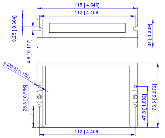
A typical system consists of stepper motor, stepper motor driver, power supply and controller. The following image shows a typical connection schematic:
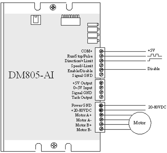
0 – 5 V Speed Mode

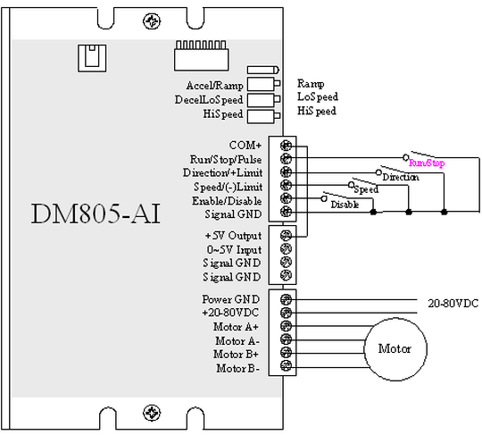
Low / High Speed Mode
External POT Mode
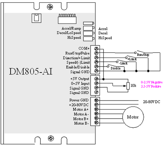
Pulse/Direction Mode
