Servo Motor Driver Leadshine ACS806
 Download data sheet Download Hardware Manual Download Software Manual
 Download ProTuner SoftwareDownload Configuration file for ACM602/604-01-2500 motorsDownload RS232 pin layout
Leadshine's fully digital AC servo drive ACS806 is developed with 32-bit DSP based on advanced control algorithm. Since its input commands are PUL/DIR signals, the users can upgrade stepping drives to the ACS806 without changing control systems. The ACS806 can offer high precision, high speed and high reliability performance, and is widely used in inkjet printers, engraving machines, and etc. A built-in controller can be used for testing and tuning. PC based and handheld configuration & tuning tools can meet different tuning environments or requirements.
- Input: 18 - 80VDC
- Peak Current: 18A , Continuous Current: 6 A (Max), 50 - 400 W
- FOC-SVPWM technologies
- PC based and handheld configuration tools
- Electronic gear rate from 1/255 to 255
- Self-test function with trapezoidal velocity profile
- Support PUL/DIR and CW/CCW control signals
- Opto-isolated, support single-ended and differential inputs
- Encoder output
- Following error lock range adjustable
- Over-voltage, over-current, encoder failure protections
- 10 latest failures self-record function
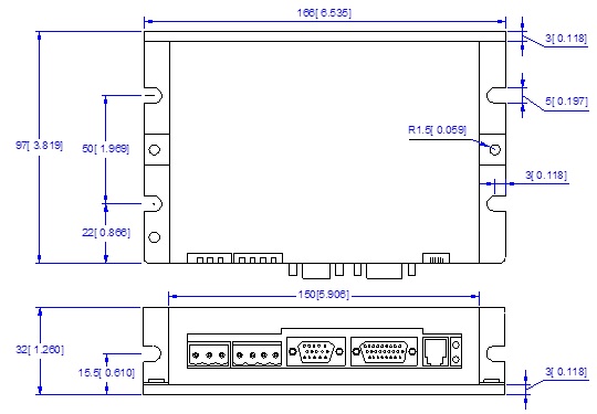
- Small size, surface-mount technology
Suitable for large and medium automation machines and equipments, such as inkjet printers, engraving machines, electronics manufacturing equipments, special NC machines, pick and place devices, packing devices, and so on. Particularly adapt to the applications require high speed, high precision, and low motor noise.
|
Parameter
|
Min
|
Typical
|
Max
|
Unit
|
|
Peak output current
|
0
|
-
|
18
|
A
|
| Continues output current |
0
|
-
|
6
|
A
|
| Supply voltage |
+18
|
-
|
+80
|
VDC
|
| Logic signal current |
7
|
10
|
16
|
mA
|
| Pulse input frequency |
0
|
-
|
600
|
kHz
|
| Insulation resistance |
500
|
-
|
-
|
MΩ
|
| Current provided to encoder |
-
|
-
|
100
|
mA
|
- Position following error : +/-1 count
- Velocity accuracy: +/-2rpm
- Maximum acceleration speed (No Load) : 80 rpm/ms2
- Input frequency up to 600 kHz
- Maximum speed : 4000 rpm
- Allowable low speed reaches1 rpm
- Positioning accuracy :+/-1 count
- Suitable for 18 - 80 VDC AC servo motors
|
Cooling |
Natural cooling or forced cooling |
|
|
Operating |
Environment |
Avoid dust, oil, fog and corrosive gases |
|
Ambient Temperature |
0℃ - 50℃ (32℉ - 122℉) |
|
|
Humidity |
40%RH - 90%RH |
|
|
Vibration |
5.9 m/s2 Max |
|
|
Storage Temperature |
-20 ℃ - 65 ℃ (-4 ℉ - 149 ℉) |
|
|
Weight |
450 g (15.88 oz) |
|
|
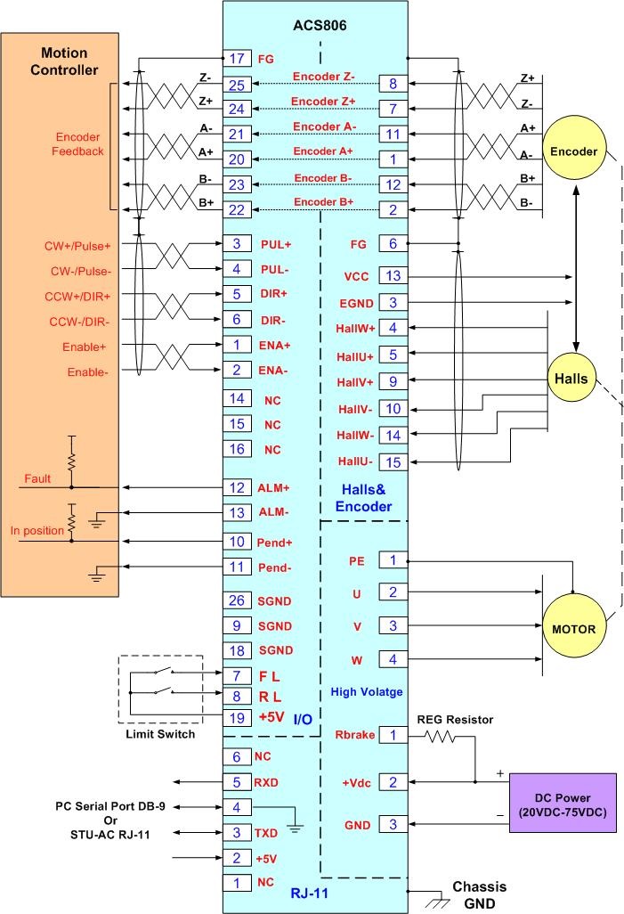
Digital & Analog I/O Connector (D-Sub 26) |
|||
|
Pin |
Signal |
Description |
I/O |
|
1 |
ENA+ |
Enable signal input + |
I |
|
2 |
ENA- |
Enable signal input - |
I |
|
3 |
PUL+ |
Pulse signal input + |
I |
|
4 |
PUL- |
Pulse signal input - |
I |
|
5 |
DIR+ |
Direction signal input + |
I |
|
6 |
DIR- |
Direction signal input - |
I |
|
7 |
FL |
Positive limit signal input |
I |
|
8 |
RL |
Negative limit signal input |
I |
|
9 |
SGND |
Signal ground |
GND |
|
10 |
Pend+ |
In position signal output+ |
O |
|
11 |
Pend- |
In position signal output- |
O |
|
12 |
ALM+ |
Alarm output signal+ |
O |
|
13 |
ALM- |
Alarm output signal- |
O |
|
14 |
NC |
Not connected |
- |
|
15 |
NC |
Not connected |
- |
|
16 |
NC |
Not connected |
- |
|
17 |
FG |
Ground terminal for shield |
GND |
|
18 |
SGND |
Signal ground |
GND |
|
19 |
+5V |
+5V@10mA power supply |
O |
|
20 |
A+ |
Encoder channel A+ output |
O |
|
21 |
A- |
Encoder channel A- output |
O |
|
22 |
B+ |
Encoder channel B+ output |
O |
|
23 |
B- |
Encoder channel B- output |
O |
|
24 |
Z+ |
Encoder channel Z+ output |
O |
|
25 |
Z- |
Encoder channel Z- output |
O |
|
26 |
SGND |
Signal ground |
GND |
|
Halls & Encoder Connector (D-Sub 15) |
|||
|
Pin |
Signal |
Description |
I/O |
|
1 |
EA+ |
Encoder channel A+ input |
I |
|
2 |
EB+ |
Encoder channel B+ input |
I |
|
3 |
EGND |
Signal ground |
GND |
|
4 |
HallW+ |
Hall sensor W+ input |
I |
|
5 |
HallU+ |
Hall sensor U+ input |
I |
|
6 |
FG |
Ground terminal for shield |
GND |
|
7 |
EZ+ |
Encoder channel Z+ input |
I |
|
8 |
EZ- |
Encoder channel Z- input |
I |
|
9 |
HallV+ |
Hall sensor V+ input |
I |
|
10 |
HallV- |
Hall sensor V- input |
I |
|
11 |
EA- |
Encoder channel A- input |
I |
|
12 |
EB- |
Encoder channel B- input |
I |
|
13 |
VCC |
+5V @ 100 mA max. |
O |
|
14 |
HallW- |
Hall sensor W- input |
I |
|
15 |
HallU- |
Hall sensor U- input |
I |
|
High Voltage Connector |
|||
|
Pin |
Signal |
Description |
I/O |
|
1 |
PE |
Motor case ground |
GND |
|
2 |
U |
Motor phase U |
O |
|
3 |
V |
Motor phase V |
O |
|
4 |
W |
Motor phase W |
O |
|
5 |
Rbrake |
Brake resistor connection (VDC-RBrake) |
I |
|
6 |
+Vdc |
DC power Input (18-80 VDC) |
I |
|
7 |
GND |
Power Ground |
GND |
|
RS232 Communication Connector |
|||
|
Pin |
Signal |
Description |
I/O |
|
1 |
NC |
Not connected |
- |
|
2 |
+5V |
+5V power only for STU |
O |
|
3 |
TxD |
RS232 transmit |
O |
|
4 |
GND |
Ground |
GND |
|
5 |
RxD |
RS232 receive |
I |
|
6 |
NC |
Not connected |
- |
|
Signal |
Description |
|
ENA+/ENA- |
Enable input signal. This signal is used for enabling / disabling the drive. High level for enabling the drive and low level for disabling the drive. Usually left UNCONNECTED (ENABLED). |
|
PUL+/PUL- |
Pulse input signal. In single pulse (pulse/direction) mode, this input represents pulse signal, each rising or falling edge active (software configurable); 4-5V when PUL-HIGH, 0-0.5V when PUL-LOW. In double pulse mode (pulse/pulse) , this input represents clockwise (CW) pulse,active at both high level and low level . For reliable response, pulse width should be longer than 0.85μs. Series connect resistors for current-limiting when +12V or +24V used. The same as DIR and ENA signals. |
|
DIR+/DIR- |
Directions input signal. In single-pulse mode, this signal has low/high voltage levels, representing two directions of motor rotation; in double-pulse mode (software configurable), this signal is counter-clock (CCW) pulse,active at both high level and low level. For reliable motion response, DIR signal should be ahead of PUL signal by 5μs at least. 4-5V when DIR-HIGH, 0-0.5V when DIR-LOW. |
|
FL/RL |
Positive or negative limit input signal. Use signal ground for reference. 0-0.5V is Low level input and 4-5V is High Level input. The active level can be set with configuration tools such as ProTuner, STU-ACS. If active at low level, FL/RL must be kept at high level for normal drive operation, and the drive will short-circuit the motor coils to stop the motor immediately when FL/RL turn to low level. If active at high level, FL/RL must be kept at low level for normal drive operation, and the drive will short-circuit the motor coils to stop the motor immediately when FL /RL turn to high level. Please select active at high level when RL/RL is not connected. |
|
Pend+/Pend- |
In position signal output. OC output, high impedance when the position error is more than 2 pulses and low impedance when the position error is less than 2 pulses. |
|
ALM+/ALM- |
Alarm signal output. OC output, high impedance when the working status is normal and low impedance when over-voltage, over-current, phase error, encoder error, limit error, position following error happens. |
|
A+/A-/B+ /B-/Z+/Z- |
Encoder feedback signals output, usually offered to the controller for external velocity/position loop. |
|
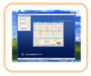
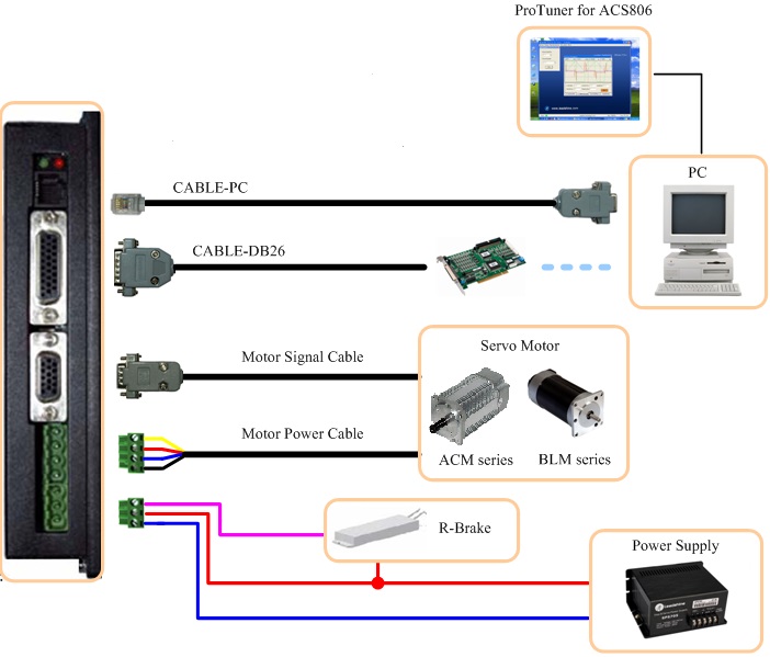
ProTuner |
|
|
Description |
PC-based configuration & tuning software. |
|
Order |
Standard Accessory, user can download from https://mecheltron.com/en/service website for free. |
|
|
|
|
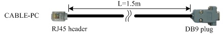
CABLE-PC |
|
|
Description |
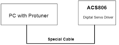
Special RS232 cable designed to setup communication between the drive and PC-based configuration & tuning software ProTuner. |
|
Order |
Standard Accessory, one is enough for a user to configure and tune multiple drives. |
|
|
|