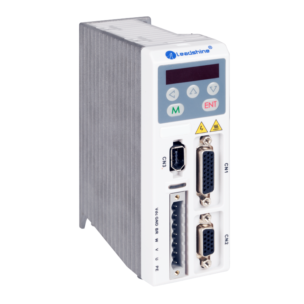

Models ELD5-400 and ELD5-750
Servo Motor Drives
Digital Technology, max. 55 V DC/ 7.0 A, 50 - 400 W/ 750 W

- Easy Tuning
- 3 different modes:
- Position Mode: To control by pulse and direction signal
- Velocity Mode: Speed control by an analog voltage input signal -10 V to +10 V, for example for applications that need constant or variable speed.
- Torque Mode: Torque control by an analog voltage input signal -10 V to +10 V for a constant torque, for example for a winding application. In case no torque inquired the max. speed to be configured by software.
- Automatic identification for motor with 17 bit or 23 bit encoder
- Simple and flexible to control
- RS485/ Modbus/ Canopen
- Notch filter, damping filter
- Optional Feedback
|
Power & Environment |
|||
|
Driver model |
ELD5-400/ ELD5-400Z |
ELD5-750/ ELD5-750Z |
|
|
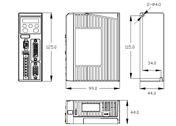
Size (mm) |
125 x 99 x 44 |
||
|
Rated Power (kw) |
0.4 |
0.75 |
|
|
Rated output current (A) |
10 |
20 |
|
|
Max. output current (A) |
30 |
60 |
|
|
Main Power |
Voltage (V) |
V DC 24 - 55 (recommended 24 - 48 V DC) |
|
|
Current (A) |
10 |
20 |
|
|
48 - 55 V DC: 7 A |
48 - 55 V DC: 14 A |
||
|
Control Power |
Voltage(V) |
DC 12 - 24 |
|
|
Current (mA) |
≥ 12 |
||
|
Control method |
IGBT PWM sinusoidal Wave Drive |
||
|
Overload |
300 % |
||
|
Brake resistor |
External Connection |
||
|
Communication Interface |
Modbus (RS232 or RS485), CANopen |
||
|
Protection Rank |
IP20 |
||
|
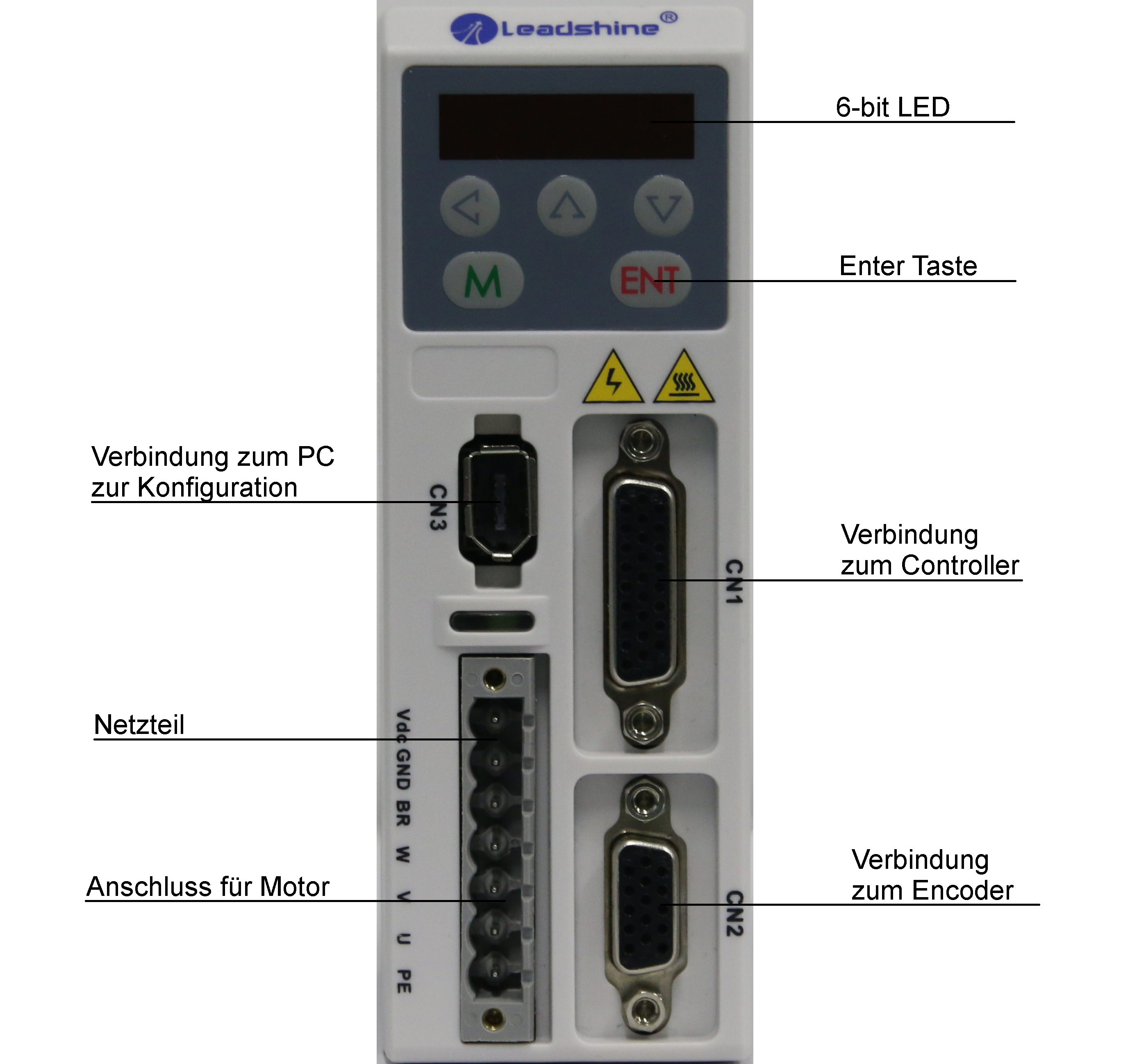
Communication & Connection |
|
|
Communication with PC |
1394a (like FireWire400) 6 pin for RS232 or RJ45 for RS485 |
|
Pulse input |
2 fast pulse input, 5 V - 24 V all compatible |
|
Pulse encoder output |
5 V differential output, A/ B/ Z phase (optional frequency divider) |
|
Digital input/ output |
4 programmable OC outputs, 5 programmable OC inputs |
|
Analog input |
1 analog input: -10 V to +10 V |
|
Feedback Supported |
1000 line or 2500 line incremental encoder (ELD5-400/ ELD5-750) |
|
Serial encoder (ELD5-400Z/ ELD5-750Z) |
|
|
Servo Driver, Storage Ambient Condition Requirement |
|
|
Item |
ELD5 series driver |
|
Temperature |
-20 - 80 ℃ |
|
Humidity |
Under 90 %RH (free from condensation) |
|
Atmospheric environment |
Indoor (no exposure) no corrosive gas or flammable gas, no oil or dust |
|
Altitude |
Lower than 1000 m |
|
Protection level |
IP00 (no protection) |
|
Servo Driver, Installation ambient condition Requirement |
|
|
Item |
ELD5 series driver |
|
Temperature |
0 - 55 ℃ |
|
Humidity |
Unter 90 %RH (free from condensation) |
|
Atmospheric environment |
Indoor (no exposure) no corrosive gas or flammable gas, no oil or dust |
|
Altitude |
under 1000 m |
|
Protection level |
IP00 (No protection) |
|
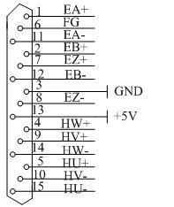
Encoder Input Port-CN2 Terminal Signal for ELD5-400/ ELD5-750 |
|||
|
Pin |
Schema |
Signal |
Name |
|
1 |
|
EA+ |
Encoder channel A+ input |
|
2 |
EB+ |
Encoder channel B+ input |
|
|
3 |
EGND |
Signal gound |
|
|
4 |
Hall W+ |
Hall sensor W+ input |
|
|
5 |
Hall U+ |
Hall sensor U+ input |
|
|
6 |
FG |
Ground terminal for shielded |
|
|
7 |
EZ+ |
Encoder channel Z+ input |
|
|
8 |
EZ- |
Encoder channel Z- input |
|
|
9 |
Hall V+ |
Hall sensor V+ input |
|
|
10 |
Hall V- |
Hall sensor V- input |
|
|
11 |
EA- |
Encoder channel A- input |
|
|
12 |
EB- |
Encoder channel B- input |
|
|
13 |
VCC |
+5 V for encoder power supply |
|
|
14 |
Hall W- |
Hall sensor W- input |
|
|
15 |
Hall U- |
Hall sensor U- input |
|
|
Encoder Input Port-CN2 Terminal Signal for ELD5-400Z/ ELD5-750Z |
||
|
Pin |
Signal |
Name |
|
3 |
EGND |
Signal ground |
|
9 |
SD+ |
Encoder Signal |
|
10 |
SD- |
|
|
13 |
VCC |
+5 V for encoder power supply |
|
|
BAT+ |
Only available for multi-turn absolute encoder |
|
BAT- |
||
|
Control Signal Port CN1 |
|||||
|
Pin |
Schema |
Signal |
E/A |
Detail |
|
|
1 |
|
COM+ |
Input |
Power supply positive terminal of the external input control signal, |
|
|
2 |
SI1-Svon |
Input |
Digital input signal 1, default value is servo on signal in position mode, low level available in default , the maximum voltage is 24 V input. |
||
|
3 |
PUL+ |
Input |
Positive and negative pulse input, respectively. TTL level (5 V), the rising edge available in default |
||
|
4 |
PUL- |
Input |
|||
|
5 |
DIR+ |
Input |
Positive and negative direction input, respectively. TTL level (5 V), the rising edge available in default |
||
|
6 |
DIR- |
Input |
|||
|
7 |
SI2-FL |
Input |
Digital input signal 2, default value is forward run prohibited (POT) signal in position mode, low level available in default, max voltage is 24 V input |
||
|
8 |
SI3-RL |
Input |
Digital input signal 3, default value is reverse run prohibited (NOT) signal in position mode, low level available in default, max voltage is 24 V input |
||
|
9 |
SI4-ZS |
Input |
Digital input signal 4, default value is zero-speed clamp (ZEROSPD) signal in position mode, low level available in default, max voltage is |
||
|
10 |
SI5-CLR |
Input |
Digital input signal 5, default value is deviation counter clear input in position mode, low level available in default, max voltage is 24 V input |
||
|
12 |
Vin+ |
Input |
Analog input, voltage input range: -10 - +10 V, input resistor 20 KΩ |
||
|
13 |
SO1-RDY |
Input |
Digital output signal 1, default value is servo ready output (S-RDY) in position mode |
OC, the maximum voltage / current is no more than 30 V,
Recommend voltage: 12 V - 24 V.
Current: 10 mA |
|
|
14 |
SO2- ALM |
Ausgang |
Digital output signal 2, default value is alarm output (ALM) in position mode |
||
|
15 |
SO3- INP |
output |
Digital output signal 3, default value is positioning complete (INP) in position mode |
||
|
16 |
SO4- BRK |
output |
Digital output signal 4, default value is external brake release output (BRK-OFF) in position mode |
||
|
17 |
NC |
|
|
||
|
18 |
COM- |
output |
Digital output signal commonality ground |
||
|
19 |
+5 V |
output |
Encoder signal output +5 V, 50 mA |
||
|
20 |
A+ |
output |
Positive/ negative differential output terminal of motor encoder A phase |
||
|
21 |
A- |
output |
|||
|
22 |
B+ |
output |
Positive/ negative differential output terminal of motor encoder B phase |
||
|
23 |
B- |
output |
|||
|
24 |
Z+ |
output |
Positive/ negative differential output terminal of motor encoder Z phase |
||
|
25 |
Z- |
output |
|||
|
26 |
GND |
output |
Ground |
||

|
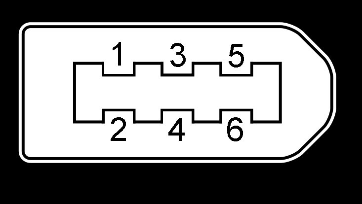
Communication Port CN3 |
|||
|
RS232 |
To connect a PC or an STU, use a special serial cable what is prohibited to be connected when the device is power on. It is recommended to use a twisted pair or a shielded cable less than 2 meters in length.. |
||
|
RS485 |
Recommend shielded twisted-pair |
||
|
Pin |
Schema |
Signal |
Name |
|
1 |
|
GND |
Ground |
|
2 |
TxD |
sending terminal of RS232 |
|
|
3 |
5V |
Reserved, the current is less than 50mA |
|
|
4 |
RxD |
received terminal of RS232 |
|
|
5 |
RS485+ |
Ground |
|
|
6 |
RS485- |
sending terminal of RS232 |
|
|
Main Power Input Port CN4 |
|||
|
Pin |
Schema |
Signal |
Name |
|
1 |
|
V DC |
+24 V ~ +55 V |
|
2 |
GND |
Power Ground |
|
|
3 |
RBr |
Brake Input |
|
|
4 |
W |
Motor W |
|
|
5 |
V |
Motor V |
|
|
6 |
U |
Motor U |
|
|
7 |
PE |
Shield |
|

|
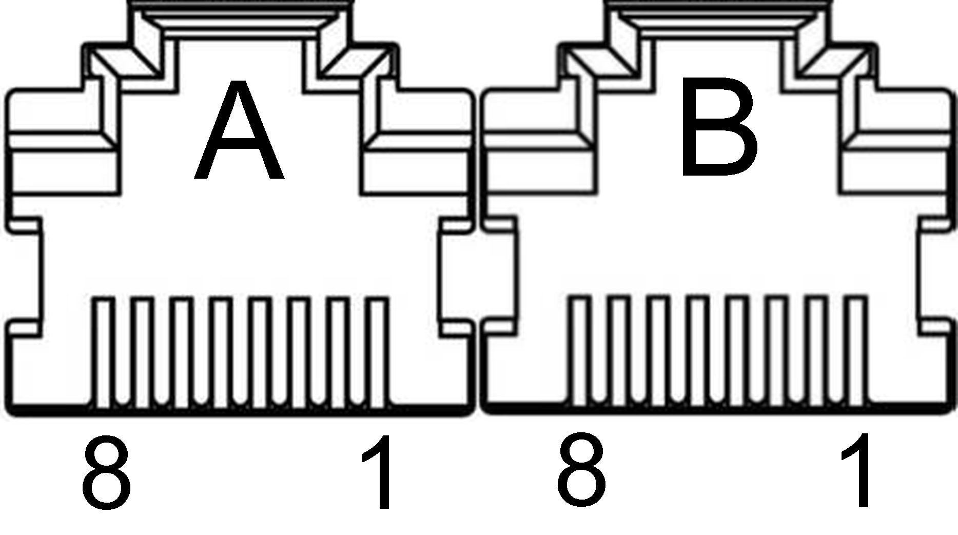
Bus Connector CN5 |
|||
|
Pin |
Schema |
Signal |
Detail |
|
A-1 |
|
RS485+ |
485data+ |
|
A-2 |
RS485- |
485 data- |
|
|
A-3 |
GND |
Ground |
|
|
A-7 |
GND |
Ground |
|
|
B-1 |
RS485+ |
485data+ |
|
|
B-2 |
RS485- |
485 data- |
|
|
B-3 |
GND |
Ground |
|
|
B-7 |
GND |
Ground |
|
For motors with 1000 line or 2500 line incremental encoders, the values Pr715 and Pr716 must be changed in the software or the keypad as shown in the table below. Motors with a 5000 line, 17 bit or 23 bit absolute encoders are detected automatically.
|
Motor Type |
Pr715 |
Pr716 |
Motor Type |
Pr715 |
Pr716 |
|
ACM602V36-01-1000 |
1 |
33 |
ACM4010V24-T-2500 |
9 |
4 |
|
ACM604V36-01-1000 |
2 |
33 |
ACM602V36-T-2500 |
6 |
36 |
|
57BL180D-1000 |
3 |
33 |
ACM602V24-T-2500 |
7 |
36 |
|
BLM57180-1000 |
ACM604V48-T-2500 |
||||
|
ACM4005V24-T-2500 |
8 |
4 |
ACM604V60-T-2500 |
0 |
36 |
The number of pulses per revolution can be set with the software or keypad using parameters PA_009 and PA_010 according to the manual.
Position Mode
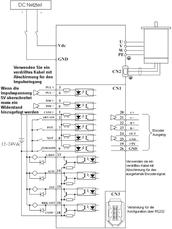
Position Mode wiring
Torque / Velocity Mode
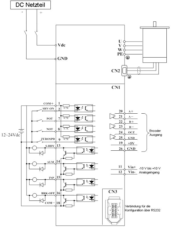
Torque/ Velocity Mode wiring
