
Hybrid Servo Driver
Leadshine ES-DH2306
 Download Data Sheet
 Download ProTuner ES-D Software Download Hardware Manual Download Software Manual
The ES series offers an alternative for applications requiring high performance and high reliability when the servo was the only choice, while it remains cost-effective. The system includes a 3-phase stepper motor combined with a fully digital, high performance drive and an internal encoder which is used to close the position, velocity and current loops in real time, just like servo systems. It combines the best of servo and stepper motor technologies, and delivers unique capabilities and enhancements over both, while at a fraction of the cost of a servo system.
- Closed-loop, eliminates loss of steps or movement synchronization
- Operating voltage: 150 - 230 VAC or 212 - 325 VDC
- Excellent response time, quick acceleration, and very high high-speed torque (30% more as open-loop)
- Load based output current of 0.5 - 6.0 A (PEAK)
- Significantly reduced motor heating and more efficiency
- Smooth motor motion and low motor noise
- Does not need a high torque margin
- No tuning for plug and play setup, and always stable
- Fast response, no delay and almost no settle time
- High torque at starting and low speed, high stiffness at standstill
- On-board LED panel for custom configuration and motion mode display
- Over voltage, over-current, and position-error protection
- Lower cost
|
Parameters
|
Min | Typical. |
Max
|
Unit |
|
Output current(PEAK)
|
0.5
|
-
|
6.0
|
A
|
|
Input voltage
|
150 (212)
|
180 (255)
|
230 (325)
|
VAC (VDC)
|
|
Logic signal current
|
7
|
13
|
20
|
mA
|
|
Pulse input frequency
|
0
|
-
|
200
|
kHz
|
|
Microstep resolution
|
200
|
51200 |
Steps per rev.
|
|
|
Isolation resistance
|
500
|
MΩ
|
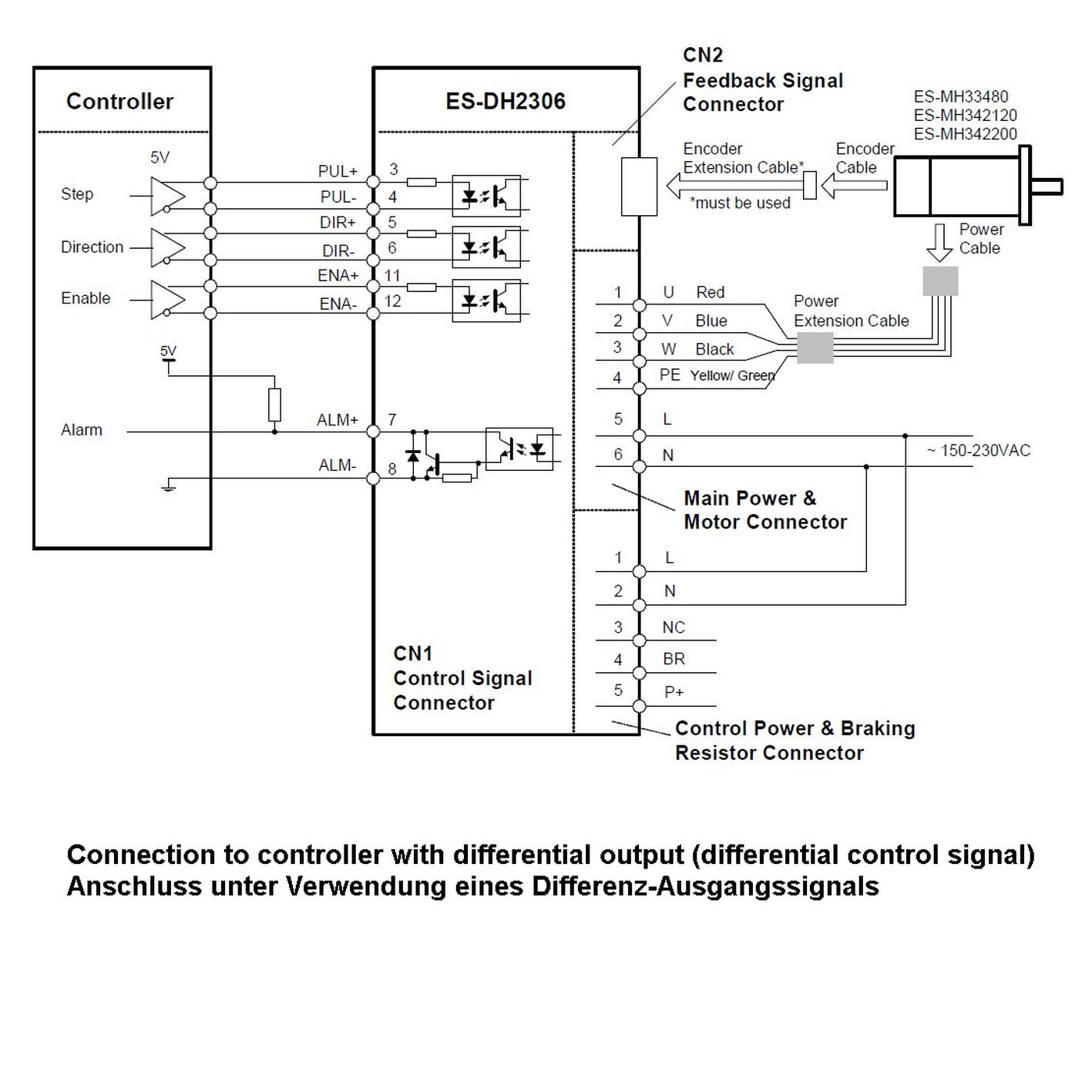
The ES-DH2306 has five connectors, each one for control signals connections, for encoder feedback, for main power supply and external braking resistor, control power supply and motor connection, and for RS232 communication.
|
Control Signal Connector - D-Sub, 44 pins, female
|
|||
|
Pin
|
Name
|
I/O
|
Description
|
|
1-2
|
PUL+
|
I
|
not connected
|
|
3
|
PUL+
|
I
|
Pulse signal: In single pulse (pulse/direction) mode, this input represents pulse signal, each rising or falling edge active (software configurable, see hybrid servo software operational manual for more detail); In double pulse mode (software configurable), this input represents clockwise (CW) pulse, active both at high level and low level. 4-5V when PUL-HIGH, 0-0.5V when PUL-LOW. For reliable response, pulse width should be longer than 10μs. Series connect resistors for current-limiting when +12V or +24V used. The same as DIR and ENA signal.
|
|
4
|
PUL-
|
I
|
|
|
5
|
DIR+
|
I
|
Direction signal: In single-pulse mode, this signal has low/high voltage levels, representing two directions of motor rotation. In double-pulse mode (software configurable), this signal is counter-clock (CCW) pulse, active both at high level and low level. For reliable motion response, DIR signal should be ahead of PUL signal by 5μs at least. 4-5V when DIR-HIGH, 0-0.5V when DIR-LOW. Please note that rotation direction is also related to motor-driver wiring match. Exchanging the connection of two wires for a coil to the driver will reverse motion direction. The direction signal’s polarity is software configurable.
|
|
6
|
DIR-
|
I
|
|
|
7
|
ALM+
|
I
|
Enable signal: OC output signal, active when one of the following protection is activated: over-voltage, over current, braking error and position following error. This port can sink or source max. 100mA current at 5V. The active level of alarm signal is software configurable.
|
|
8
|
ALM-
|
I
|
|
|
9-10
|
|
|
not connected
|
|
11
|
ENA+
|
I
|
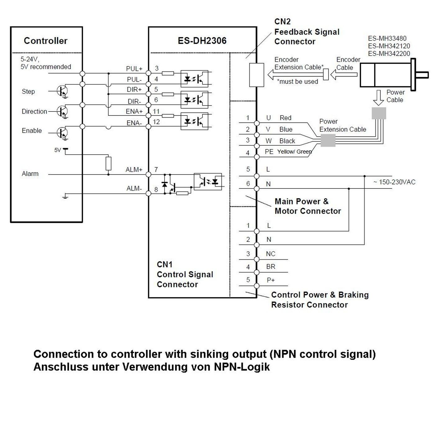
Enable signal: This signal is used for enabling/disabling the driver. By default, high level for enabling the driver and low level for disabling the driver (@ NPN control signal). It’s usually left UNCONNECTED (ENABLED). Please note that PNP and Differential control signals are on the contrary, namely low level for enabling. The active level of ENA signal is software configurable.
|
|
12
|
ENA-
|
I
|
|
|
13-14
|
|
|
not connected
|
|
Encoder Feedback Connector
|
|||
|
Pin
|
Name
|
I/O
|
Description
|
|
1
|
EA+
|
I
|
Encoder channel A+ input
|
|
2
|
EB+
|
I
|
Encoder channel B+ input
|
|
3
|
EGD
|
GND
|
Signal ground
|
|
4
|
HW
|
I
|
Reserved
|
|
5
|
HU
|
I
|
Reserved
|
|
6
|
FG
|
GND
|
Ground terminal for shield
|
|
7
|
EZ+
|
I
|
Reserved
|
|
8
|
EZ-
|
I
|
Reserved
|
|
9
|
HV
|
I
|
Reserved
|
|
10
|
NC
|
-
|
Not Connected
|
|
11
|
EA-
|
I
|
Encoder channel A- input
|
|
12
|
EB+
|
I
|
Encoder channel B- input
|
|
13
|
VCC
|
O
|
+5V @ 100 mA max.
|
|
14
|
NC
|
-
|
not Connected
|
|
15
|
NC
|
-
|
not Connected
|
|
Connector for main power supply and external brake resistor
|
|||
|
Pin
|
Name
|
I/O
|
Description
|
|
1
|
L
|
I
|
Main power supply input connected to 150 – 230 VAC
|
|
2
|
N
|
I
|
|
|
3
|
NC
|
-
|
|
|
4
|
BR1
|
I
|
External brake resistor (optional, value: 100 Ω to 120 Ω, 100 W)
|
|
5
|
P+
|
O
|
Internal DC bus voltage output. The brake resistor is connected between BR1 and P+.
|
|
Control Power and Motor Connector
|
|||
|
Pin
|
Name
|
I/O
|
Description
|
|
1
|
U
|
O
|
Motor phase U
|
|
2
|
V
|
O
|
Motor phase V
|
|
3
|
W
|
O
|
Motor phase W
|
|
4
|
PE
|
-
|
Case Ground
|
|
5
|
L
|
I
|
Control power supply input 150 – 230 VAC
|
|
6
|
N
|
I
|
|
|
RS232 Communication Port
|
|||
|
Pin
|
Name
|
I/O
|
Description
|
|
1
|
GND
|
GND
|
Ground
|
|
2
|
TxD
|
O
|
RS232 transmit.
|
|
3
|
+5V
|
O
|
Reserved +5V power output (Note: Do not connect it to RS232 port)
|
|
4
|
RxD
|
O
|
RS232 receive.
|
|
5
|
NC
|
-
|
Not connected.
|
|
6
|
NC
|
-
|
Not connected.
|