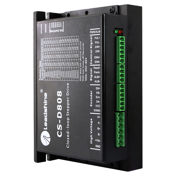

Hybrid Servo Driver
CS-D808/ CS-D1008
Digital Technology, max. 80/ 100 VDC, 8.0 A
 Download data sheet
 Download ProTuner CS-D softwareDownload user manual Download software manualDownload RS232 pin layout
Leadshine CS-D808/ CS-D1008 is a closed-loop stepper motor driver which is designed to solve the problem of step loss in open-loop stepper motor controllers and increasing system reliability with minimal cost.
The CS-D808/ CS-D1008 implements Leadshine's advanced control algorithm based on their ten years of experience in stepper motor and servo control. The CS D808/ CS-D1008 is highly reliable and competitively priced and is ideal for many industrial applications such as CNC, medical, electronics, packaging.
The CS-D808/ CS-D1008 can power 2-phase stepper motors with incremental encoders. Compared to conventional open-loop stepper motor systems, a closed-loop CS-D808/ CS-D1008 can eliminate possible step losses, perform real-time position error correction, and does not require torque reservation (100 % torque implementation). It operates the stepper motor with reduced heating, noise, vibration, etc.
- Closed-loop, eliminates loss of synchronization
- Enhance performance at low speed application ( < 60 RPM)
- No torque reservation required for readjustment control
- No Tuning required for easy commissioning
- Supply voltage CS-D808: 30 - 80 VDC, CS-D1008: 30 - 100 VDC supply voltage,
- Output current of max. 8 A
- Pulse input frequency up to max. 200 kHz
- A configurable digital output for “In Target Position Range” signal, or as brake command signal
- Micro step resolution 15 settings of 800 - 51,200 via DIP switches, or 200 - 51,200 via software (increments of 200)
- Protections for over voltage, over current and position error
|
Parameters
|
Min | Typical. |
Max
|
Unit |
|
Output current
|
0.5
|
-
|
8.0 (Peak)
|
A
|
|
Supply voltage CS-D808
|
+30
|
-
|
+80
|
VDC
|
|
Supply voltage CS-D1008
|
+30
|
-
|
+100
|
VDC
|
|
+20
|
-
|
+80
|
VAC
|
|
|
Logic signal current
|
7
|
10
|
16
|
mA
|
|
Pulse input frequency
|
0
|
-
|
200
|
kHz
|
|
Minimal pulse width
|
2.5
|
-
|
-
|
µs
|
|
Minimal direction setup
|
5.0
|
-
|
-
|
µs
|
|
Insulation resistance
|
500
|
MΩ
|
| Cooling |
Natural cooling or forced air cooling |
|
|
Operating Environment |
Environment |
Avoid dust, oil, fog and corrosive gases |
|
Ambient Temperature |
0 ℃ - 65 ℃ |
|
|
Humidity |
40 % RH - 90 % RH |
|
|
Operating Temperature |
0 - 50 °C |
|
|
Vibration |
10 - 50 Hz/ 0.15 mm |
|
| Storage Temperature |
-20 - 65 °C |
|
| Weight |
Approx. 570 g |
|
|
Control Signal Connector |
|||||||||||
|
Name |
I/O |
Description |
|||||||||
|
PUL+ |
I |
Pulse signal: (2) In double pulse control mode (CW/ CCW), set via PC software, this signal input represents a clockwise (CW) pulse and is active at both high voltage level and low voltage level. |
|||||||||
|
PUL- |
I |
||||||||||
|
DIR+ |
I |
Direction Signal: |
|||||||||
|
DIR- |
I |
||||||||||
|
ENA+ |
I |
Enable signal: This signal is used for enabling/disabling the driver. High voltage level of 4.5 - 24 V (NPN control signal) for enabling the drive and low voltage level of 0 - 0.5 VDC for disabling the driver). On the contrary please note that that PNP and Differential control signals with low voltage enable the drivers. By default, this signal is left UNCONNECTED & ENABLED. |
|||||||||
|
ENA- |
I |
||||||||||
|
Signal Connector |
|||||||||||
|
Name |
I/O |
Description |
|||||||||
|
Pend+ |
O |
Configurable Digital Output Signal: |
|||||||||
|
Pend- |
O |
||||||||||
|
ALM+ |
O |
Fault Signal: |
|||||||||
|
ALM- |
O |
||||||||||
|
Encoder Feedback Connector |
|||||||||||
|
Name |
I/O |
Description |
|||||||||
|
EB+ |
I |
Encoder channel B+ input |
|||||||||
|
EB- |
I |
Encoder channel B- input |
|||||||||
|
EA+ |
I |
Encoder channel A+ input |
|||||||||
|
EA- |
I |
Encoder channel A- input |
|||||||||
|
VCC |
O |
Encoder +5 V voltage output connection |
|||||||||
|
EGND |
GND |
Power ground connection |
|||||||||
|
Encoder Extension Cable Wire Out |
|||||||||||
|
Wire |
Color |
Name |
Description |
Wire |
Color |
Name |
Description |
||||
|
1 |
Red |
VCC |
+5 V power input |
4 |
Blue |
EA- |
Encoder Channel A- |
||||
|
2 |
White |
GND |
GND |
5 |
Yellow |
EB+ |
Encoder Channel B+ |
||||
|
3 |
Black |
EA+ |
Encoder Channel A+ |
6 |
Green |
EB- |
Encoder Channel B- |
||||
Notes:
(1) Shielding control signal wires are suggested
(2) to avoid/ reduce interference, do not tie control signal cables and power wires together
|
Power and Motor Connector |
||||
|
Pin Name |
I/O |
CS-D808 Description |
||
|
A+ |
O |
Stepper motor A+ connection Connect motor A+ wire to this pin |
||
|
A- |
O |
Stepper motor A- connection Connect motor A- wire to this pin |
||
|
B+ |
O |
Stepper motor B+ connection Connect motor B+ wire to this pin |
||
|
B- |
O |
Stepper motor B- connection Connect motor B- wire to this pin |
||
|
+V |
I |
Power supply positive connection 30 – 80 VDC power supply voltage |
||
|
GND |
GND |
Power supply ground connection |
||
|
|
|
CS-D1008 Description |
||
|
A+ |
O |
Stepper motor A+ connection Connect motor A+ wire to this pin |
||
|
A- |
O |
Stepper motor A- connection Connect motor A- wire to this pin |
||
|
B+ |
O |
Stepper motor B+ connection Connect motor B+ wire to this pin |
||
|
B- |
O |
Stepper motor B- connection Connect motor B- wire to this pin |
||
|
AC |
I |
Power supply connection |
||
|
AC |
I |
|||
|
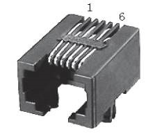
RS232 Communication Port |
||||
|
Pin |
Name |
I/O |
Description |
 |
|
1 |
NC |
- |
Not connected |
|
|
2 |
+5V |
O |
+5 V power output |
|
|
3 |
TxD |
O |
RS232 transmit |
|
|
4 |
GND |
GND |
Ground |
|
|
5 |
RxD |
I |
RS232 receive |
|
|
6 |
NC |
- |
Not connected |
|
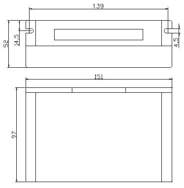
(unit: mm)
A complete closed loop stepper system should include a stepper motor with encoder, CS-D808/ CS-D1008 driver, power supply and controller (pulse generator). A typical connection is illustrated.
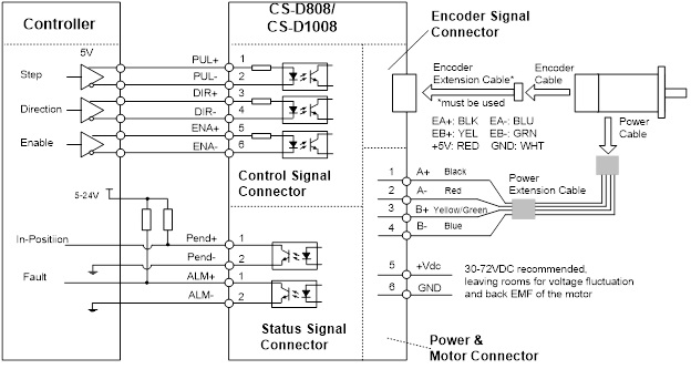
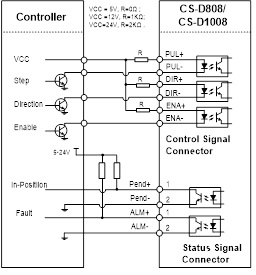
The CS-D808/ CS-D1008 can accept differential and single-ended control signal inputs (open-collector and PNP output). A CS D808/ CS-D1008 has 3 optically isolated control inputs, PUL, DIR, and ENA. Refer to the following two figures for connections of open-collector and PNP signals.
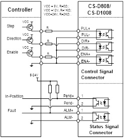 Connection to Common Cathode |
 Connection to Common Cathode |
