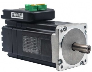
Integrated AC Servo Motors
iHSV86
 Download data sheet
 Download parameterization software
The iHSV86-XX AC servo motor consists of a perfectly tuned servo driver integrated in a servo motor, vector controlled and with DSP chip. The system saves installation space, cabling between driver, motor and encoder, and is very profitable due to its low purchase price.
- High positioning accuracy
- High torque
- Cost-effective high speed response
- Smooth and very low noise
- Compact size
- Pulse Input Mode Pulse + Direction
- Current Loop Bandwidth:(-3dB)2KHz (Typical)
- Speed Loop Bandwidth: 500Hz (Typical)
- Position Loop Bandwidth: 200Hz (Typical)
- Parameters to download via RS232 to PC.
- Users can define subdivisions via external Dial-up switches or via software.
- Over-current, I2T-motor-current-observation, Over-voltage, Under-voltage, Over-heat, Over-speed, protections.
iHSV86-XX can be used in various applications such as laser cutters, laser markers, high precision X-Y tables, labelling machines, CNC router, etc. Its unique features make the iHSV86-XX an ideal choice for applications that require low-speed smoothness and high torque at higher revolution by small mounting space.
iHSS stepper:
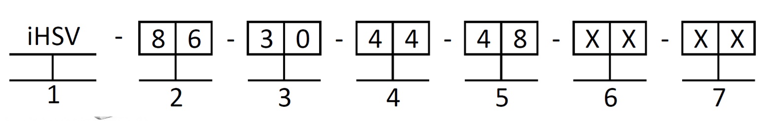
- 1. Integrated Servo motor
- 2. Motor frame size: 86 mm
- 3. Motor revolution (unit: x 100 min-1) 10 ≙ 1000 min-1, 20 ≙ 2000 min-1, 30 ≙ 3000 min-1
- 4. Output Power (unit: x 10 W) 10 ≙ 100 W; 20 ≙ 200 W; 44 ≙ 440W
- 5. Motor rated DC voltage: 24 ≙ 24 V, 36 ≙ 36 V, 48 ≙ 48V
- 6. Shaft length: : No digit ≙ 38mm
- 7. Pilot diameter: No digit at iHSV86 = 73 mm
|
Parameters: |
Min |
Typical |
Max |
Unit |
||||
|
|
iHSV86-30-44-48 |
iHSV86-30-66-72 |
iHSV86-30-44-48 |
iHSV86-30-66-72 |
iHSV86-30-44-48 |
iHSV86-30-66-72 |
|
|
|
Input Voltage : |
43 |
65 |
48 |
72 |
53 |
79 |
VDC |
|
|
Output current : |
|
|
13,1 |
13,1 |
19,6 |
19,6 |
A |
|
|
Pulse per revolution: |
4 |
|
- |
|
51200 |
|
- |
|
|
Pulse input frequency: |
|
|
- |
|
200 |
|
kHz |
|
|
Pulse Voltage |
3.3 |
|
5 |
|
24 (with R 3 - 5 kΩ) |
V |
||
|
Logic Signal Current |
7 |
|
10 |
|
16 |
|
mA |
|
|
Isolation Resistance |
100 |
|
- |
|
- |
|
MΩ |
|
|
Part Name: |
iHSV60-30-40-48 |
iHSV86-30-66-72 |
Unit |
|
|
Rated Power |
400 |
660 |
|
W |
|
Rated Torque |
1.4 |
2.1 |
|
Nm |
|
Rated Speed |
3000 |
3000 |
|
min-1 |
|
Max. Speed |
4000 |
4000 |
|
min-1 |
|
Rated Voltage |
48 |
72 |
|
V |
|
Weight |
3.5 |
4.5 |
|
kg |
| Cooling |
Natural cooling or forced air cooling |
|
|
Operating Environment |
Environment |
Avoid dust, oil, fog and corrosive gases |
|
Ambient Temperature |
0 ℃ - 40 ℃ |
|
|
Humidity |
40 %RH - 90 %RH |
|
|
Operating Temperature |
70 ℃ max |
|
| Storage Temperature |
-20 ℃ - +80 ℃ |
|
|
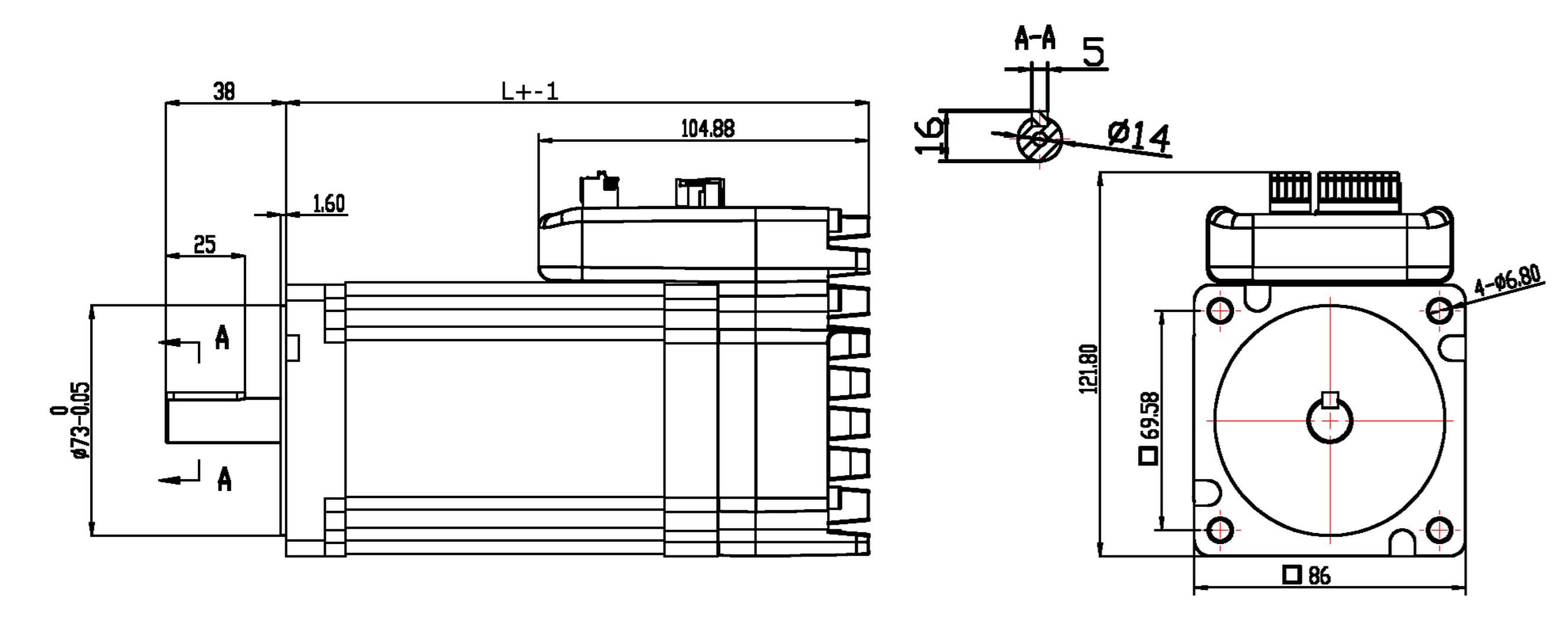
Name: |
Bore Distance |
Length of motor and drive (L) |
Shaft length |
Pilot Diameter |
|
iHSV86-30-44-48 |
69,58 mm |
158 ±1 mm |
38 ± 1mm |
73 mm |
|
iHSV86-30-66-72 |
69,58 mm |
185±1 mm |
38 ± 1mm |
73 mm |
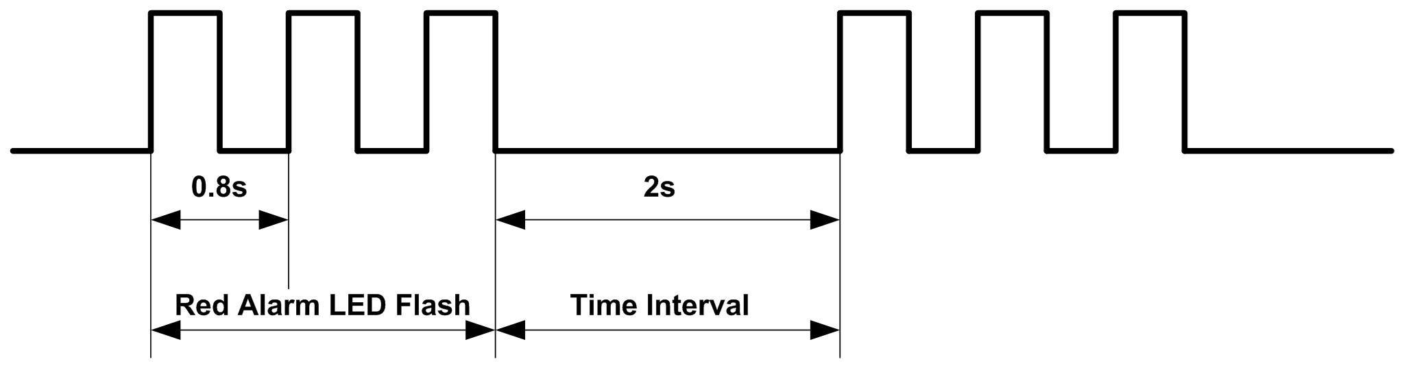
| LED light flashes | Alarm description |
| 2 times | Drive over current |
| 3 times | Driver position deviation exceeds set value |
| 4 times | Driver encoder alarm |
| 7 times | Driver overload |
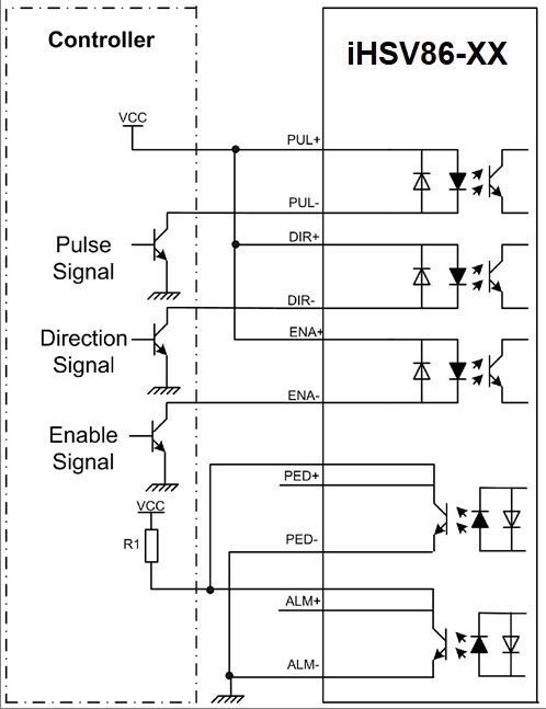
The iHSSXX have three connectors, one connector for power connections, another one for control signal connections and a third one for RS232 communication connections
|
Power Connector +VDC
|
|||
| Pin | Name | I/O | Description |
| 1 | DC+ | I | Power Supply Input (Positive) 43 – 53 / 65 - 79VDC; 48 / 72 V is typical. Recommended to leave reasonable reserve for voltage fluctuation and back-EMF during deceleration. |
| 2 | GND | GND | Power Ground (Negative) |
|
Control Signal Connector |
|||
|
Pin |
Name |
I/O |
Description |
|
1 |
ALM- |
O |
Alarm Signal: OC output signal, activated when one of the following protection is activated: over-voltage and over current error. They can sink or source MAX 8 mA current at 24 V, respectively 200 mW. The impedance between ALM+ and ALM- is high for normal operation and becomes low when any protection is activated. |
|
2 |
ALM+ |
O |
|
|
3 |
PED- |
O |
In-position Signal: OC output signal, activated when actual motor position reaches to target Position. This port can sink or source MAX 8 mA current at 24 V, respectively 200 mW. The impedance between PED+ and PED- is high for normal operation and becomes low when the target position is reached. |
|
4 |
PED+ |
O |
|
|
5 |
ENA- |
I |
Enable signal: This signal is used for enabling/disabling the drive board. By default, high level (NPN control signal) for enabling the drive board and low level for disabling the drive board. It is usually left UNCONNECTED (ENABLED). Please note that the PNP and Differential control signals are on the contrary, namely Low level for enabling. (optional: SW5 ON direction of rotation CW/CCW) |
|
6 |
ENA+ |
I |
|
|
7 |
DIR- |
I |
Direction Signal: In single-pulse mode, this signal has low/high voltage levels, representing two directions of motor rotation. For reliable motion response, DIR signal should be ahead of PUL signal by 5μs at least. 3.5-24V for DIR-HIGH, 0-0.5V for DIR-LOW. Toggle DIP switch S6 to reverse motion direction. (optional: SW5 ON direction of rotation CW/CCW) |
|
8 |
DIR+ |
I |
|
|
9 |
PUL- |
I |
Pulse Signal: In single pulse (pulse/direction) mode, this input represents pulse signal, active at each rising or falling edge (Software configurable). 3.5 – 24 V for PUL-HIGH, 0 - 0.5 V for PUL-LOW. For reliable response, pulse width should be longer than 2.5μs for 200kHz MAX input frequency. |
|
10 |
PUL+ |
I |
|
|
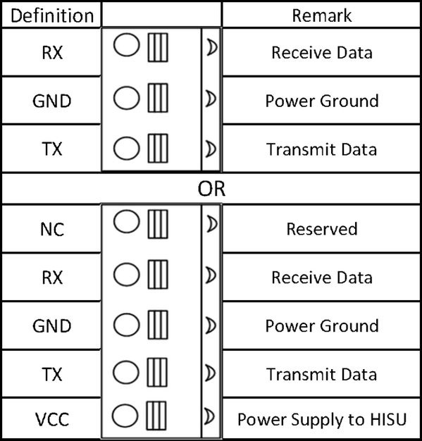
RS232 Communication Connector
|
||||
| Pin | Name | Colors at the beige round cable | Colors at the grey flat cable | Description |
| 1 | NC | - | - | Not Connected |
| 2 | RX | Brown-White | Yellow | RS232 Receive data |
| 3 | GND | Blue | Green | Ground |
| 4 | TX | Blue-White | Red | Transmit data |
| 5 | VCC | - | - | Power Supply 3.3 V to HISU. For PC software use unconnected. |
Note 1: The RS232 communication port is not isolated. Please use an isolated power supply for the iHSV-XX when the PC’s serial port is not isolated.
Note 2: Do not plug or unplug the connector when power is on.
Pulses / Rev. (SW 1-SW 4)
Pulses per revolution of the iHSS-XX can be configured via DIP switch SW1-SW4 or by the tuning software. When all SW1-SW4 are at “ON” positions, the drive will take the setting set by the software. In this case, a user can re-configure to any value between 4 and 51200 through software. If any bit of SW1-SW4 is at “OFF” position, the integrated drive board will take micro step resolution setting determined by bit positions of SW1-SW4. Use the following table for their resolution settings via the DIP switches.
|
Pulses / Revolution
|
SW1
|
SW2
|
SW3
|
SW4
|
|
Software Configured
|
On
|
On
|
On
|
On
|
|
800 |
Off |
On |
On |
On |
|
1600 |
On |
Off |
On |
On |
|
3200 |
Off |
Off |
On |
On |
|
6400 |
On |
On |
Off |
On |
|
12800 |
Off |
On |
Off |
On |
|
25600 |
On |
Off |
Off |
On |
|
51200 |
Off |
Off |
Off |
On |
|
1000 |
On |
On |
On |
Off |
|
2000 |
Off |
On |
On |
Off |
|
4000 |
On |
Off |
On |
Off |
|
5000 |
Off |
Off |
On |
Off |
|
8000 |
On |
On |
Off |
Off |
|
10000 |
Off |
On |
Off |
Off |
|
20000 |
On |
Off |
Off |
Off |
|
40000 |
Off |
Off |
Off |
Off |
SW 5: With SW5 the pulse mode can be configured. OFF (off) stands for PUL/DIR mode. ON (on) for CW/CCW
SW 6: is used for setting the running direction, “off” means CCW, while “on” means CW.
SW 7: is used for PUL Filter Setting, “off” means Max. PUL frequency is 200 kHz, on means Max. PUL frequency is 100 kHz. Note: When the P22 parameter is 0, the pulse filtering degree is controlled by the SW7 pulse interference filtering dialling code, when set to other non-zero values, SW7 does not work.
SW 8: is used for PUL Smoothing Setting, “off” means switch off PUL Smoothing, “on” means switch on PUL Smoothing.
Standard parameters are already set ex works. These standard parameter values are optimized and suitable for most industrial applications. In most cases it is not necessary to change them. However, if you want to optimize the performance for your application, the software can be used to adjust these parameters
Connection to Common Anode
Connection to Common Cathode
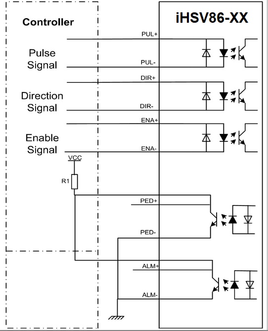
Connection to Differential Signal
Note1: : The RS232 communication port is not isolated. Please use a galvanically isolated power supply for the iHSS86-XX when the PC’s serial port is not isolated.
Note2: Do not plug or unplug the connector when power is on.