
Leadshine Integrated Stepper Motor
iST-2320
 Download data sheet
 Download ProTuner Software
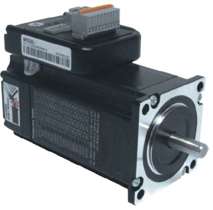
Leadshine’s iST-23xx integrated steppers are NEMA 23 stepper motors with an advanced DSP stepper drive integrated. At very compact size and with all components integrated, the iST-23xx can save mounting space, eliminate motor wiring time, reduce interferences, and cut/reduce cable and labor costs. By adopting Leadshine’s latest current control technology, the iST-23xx work with high precision, smooth movement, and extra low noise at low speed movement with no obvious resonance area.
- Integrated compact size for saving mounting space & setup time, and reducing electrical interference
- Anti-Resonance provides optimal torque and nulls mid-range instability
- Motor auto-identification and parameter auto-configuration technology
- Multi-Stepping allows a low resolution step input to produce a higher micro step output
- Smooth motor movement with no vibration
- Input voltage from 18 to 50 VDC (20-36VDC recommended)
- Motor current programmable by software from 0.5A to 6.0A. It can also be set via DIP switches.
- 0.9 - 2.0 Nm (126 – 285 oz-in) holding torque stepper motor with NEMA 23 frame size installation
- 15 micro step resolution options via DIP switches; or any value from 200 -51.200 (increased by 1) via software configuration
- Soft-start with no “jump” when powered on
- Automatic idle-current reduction (Red. rate can be software configured)
- Isolated control inputs of Pulse, Direction and Enable
- Pulse input frequency can be 200 kHz or 500 kHz (Software-configured)
- Pulse input mode can be PUL/DIR or CW/CCW (Software-configured)
- Fault outputs to external motion controllers for complete system controls.
- Over voltage and over-current protection
Leadshine’s iST-23xx can be used in various applications such as laser cutters, laser markers, high precision X-Y tables, labeling machines, CNC router, etc. Its unique features make the iST-23xx an ideal choice for applications that require both low-speed smoothness and small mounting space.
Electrical Specifications of Drive:
|
Parameter
|
Min
|
Typisch
|
Max
|
Unit
|
|
Input Voltage
|
18
|
36
|
50
|
VDC
|
| Output Current |
0.5
|
4.8 (Peak)
|
6.0 (Peak)
|
A
|
| Pulse Input Frequency |
0
|
bis zu 200
|
500
|
kHz
|
| Pulse Voltage |
3.3
|
5
|
24
|
V
|
| Logic Signal Current |
7
|
10
|
16
|
mA
|
| Isolation Resistance |
100
|
-
|
-
|
MΩ
|
Operating Environment:
| Cooling |
Natural cooling or forced cooling |
|
|
Operating Environment |
Environment |
Avoid dust, oil, fog and corrosive gases |
|
Ambient Temperature |
0 ℃ - 40 ℃ (32 ℉ - 104 ℉) |
|
|
Humidity |
40 %RH - 90 %RH |
|
|
Operating Temperature(Heat Sink) |
max. 70 ℃ (158 ℉) |
|
| Storage Temperature |
-20 ℃ - 65 ℃ (-4℉ - 149℉) |
|
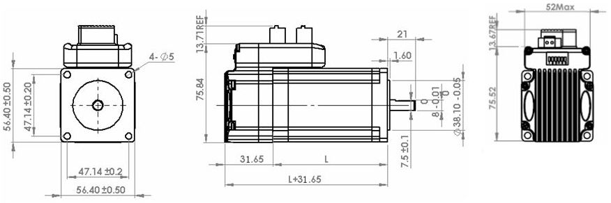
| Part Number | Holding Torque | Motor Length ( L) | Length of Motor + Drive | Weight |
| iST-2309 | 0.9 Nm | 56 mm | 87,65 mm | 0.84 kg |
| iST-2320 | 2.0 Nm | 80 mm | 111,65 mm | 1.25 kg |
The green light turns on when the iST-23xx is powered on and functions normally. In any case that drive protection is activated, the red LED blinks periodically (in every 4 seconds) to indicate the error type. In each blink, red light is on for 0.2 seconds and then off for 0.3 seconds.
| Priority | Time(s) of Blink | Sequence wave of red LED | Description |
| 1st | 2 |
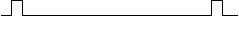 |
Over-current protection activated when peak current is more than 18A |
| 2nd | 2 |
 |
Over-voltage protection activated when drives working voltage is greater than 60±2 VDC |
Leadshine’s iST-23xx has three connectors, one connector for power connections, another one for control signal connections and a third one for RS232 communication connections.
|
Power Connector
|
|||
| Pin | Name | I/O | Description |
| 1 | +Vdc | I | Power Supply Input (Positive) 20 – 36 VDC recommended, leaving reasonable reservation for voltage fluctuation and back-EMF during deceleration. |
| 2 | GND | GND | Power Ground (Negative) |
CONNECTORS AND PIN ASSIGNMENT (CONTINUED)
|
Control Signal Connector
|
|||
|
Pin |
Name |
I/O |
Description |
|
1 |
PUL+ |
I |
Pulse signal: In single pulse (pulse/direction) mode, this input represents pulse signal, active at each rising or falling edge (software configurable). In double pulse mode (software configurable), this input represents clockwise (CW) pulse, active both at each high level and low level. 4.5 - 24 V for PUL-HIGH, 0 - 0.5 V for PUL-LOW. For reliable response, pulse width should be longer than 2.5 μs for 200K MAX input frequency or 1 μs for 500K MAX input frequency. |
|
2 |
PUL- |
I |
|
|
3 |
DIR+ |
I |
Direction Signal: In single-pulse mode, this signal has low/high voltage levels, representing two directions of motor rotation. In double-pulse mode (software configurable), this signal is counter-clock (CCW) pulse, active both at high level and low level. For reliable motion response, DIR signal should be ahead of PUL signal by 5μs at least. 4.5 – 24 V for DIR-HIGH, 0 - 0.5 V for DIR-LOW. The motor direction can also be changed by DIP switch S5. |
|
4 |
DIR- |
I |
|
|
5 |
ENA+ |
I |
Enable signal: This signal is used for enabling/disabling the drive board. By default, high level (NPN control signal) for enabling the drive board and low level for disabling the drive board. It is usually left UNCONNECTED (ENABLED). Please note that the PNP and Differential control signals are on the contrary, namely Low level for enabling. The active level of ENA signal is software configurable. |
|
6 |
ENA- |
I |
|
|
7 |
PED+ |
- |
Not connected. |
|
8 |
PED- |
- |
|
|
9 |
ALM+ |
O |
Alarm Signal: OC output signal, activated when one of the following protection is activated: over-voltage and over current error. They can sink or source MAX 20mA current at 24V. By default, the impedance between ALM+ and ALM- is low for normal operation and becomes high when any protection is activated. The active impedance of alarm signal is software configurable. |
|
10 |
ALM- |
O |
|
|
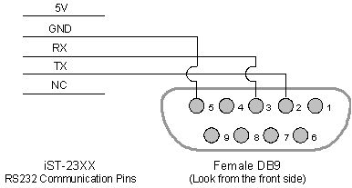
RS232 Communication Connector
|
|||
| Pin | Name | I/O | Description |
| 1 | 5V | O | +5V power output ( Note: To be left unconnected whenconnct to a PC’s serial port) |
| 2 | Tx | O | RS232 transmit. |
| 3 | GND | GND | Ground |
| 4 | Rx | I | RS232 receive. |
| 5 | NC | - | Not connected. |
Default motor current setting of iST-23xx is 4.8A peak and it reduces to 50% automatically 400ms after the last pulse.
Micro Step Resolution (S1-S4)
Micro step resolution of the iST-23xx can be configured via DIP switch S1-S4 or Leadshine’s tuning software ProTuner. When all S1-S4 are at “ON” positions, the drive will take the micro step resolution setting set by the software (4000 by default). In this case, a user can re-configure the resolution to any value between 200 and 512,000 (increased by 1) through software. If any bit of S1-S4 is at “OFF” position, the integrated drive board will take micro step resolution setting determined by bit positions of S1-S4. Use the following table for their resolution settings via the DIP switch.
Micro Step Resolution
|
Steps/Revolution
|
S1
|
S2
|
S3
|
S4
|
|
Software Configured(Default 400)
|
On
|
On
|
On
|
On
|
|
800 |
Off |
On |
On |
On |
|
1600 |
On |
Off |
On |
On |
|
3200 |
Off |
Off |
On |
On |
|
6400 |
On |
On |
Off |
On |
|
12800 |
Off |
On |
Off |
On |
|
25600 |
On |
Off |
Off |
On |
|
51200 |
Off |
Off |
Off |
On |
|
1000 |
On |
On |
On |
Off |
|
2000 |
Off |
On |
On |
Off |
|
4000 |
On |
Off |
On |
Off |
|
5000 |
Off |
Off |
On |
Off |
|
8000 |
On |
On |
Off |
Off |
|
10000 |
Off |
On |
Off |
Off |
|
20000 |
On |
Off |
Off |
Off |
|
40000 |
Off |
Off |
Off |
Off |
Motor Shaft Direction (S5)
DIP switch S5 is used for changing motor shaft rotation direction. Changing position from “ON” to “OFF”, or “OFF” to “ON” will reverse rotation direction of the iST-23xx.
Self-Test (S6)
By default, DIP switch S6 is OFF (Normal Mode) and the iST-23xx responses to any pulse input. If it is turned ON, the iST-23xx goes into self-test mode. In self-test mode, the motor shaft rotates 1 revolutions CW and then 1 revolutions CCW. The self-motion repeats until S6 is turned OFF (the motor shaft will stop immediately). Note that you are unable to communicate with the iST-23xx via the RS232 port when it is in self-test mode.
FINE TUNING:
Leadshine already loads default current-loop parameters for the iST-23xx. Those default parameter values have been optimized. They should be good enough for most industrial applications, and there is no need to tune them. However, if you want to fine tune the iST-23xx for best performance for your applications, Leadshine also offers tuning software, ProTuner, which allows you to adjust those current-loop parameters.
TYPICAL CONNECTIONS:
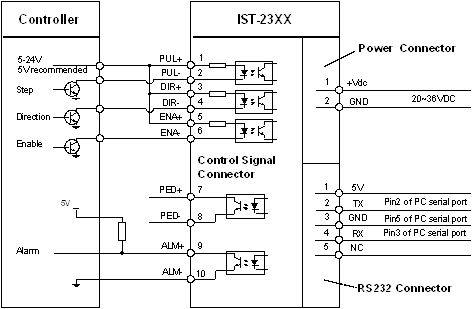
Connect IST-23XX to controller of sinking output
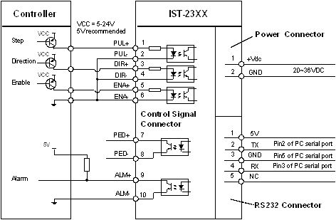
Connect IST-23XX to controller of sourcing output
TYPICAL CONNECTIONS (CONTINUED):
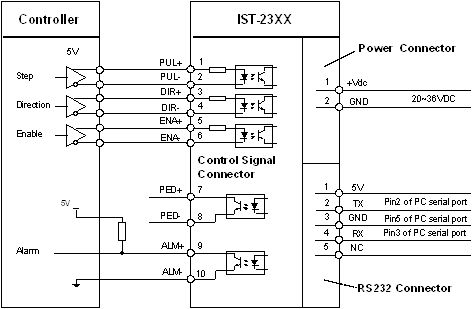
Connect IST-23XX to controller of differential output
RS232 COMMUNICATION CABLE CONNECTIONS:
Note1: The RS232 communication port is not isolated. Please use a galvanically isolated power supply for the iST-23xx when the PC’s serial port is not isolated.
Note2: Do not plug or unplug the connector when power is on.